Assembly of the elctronics

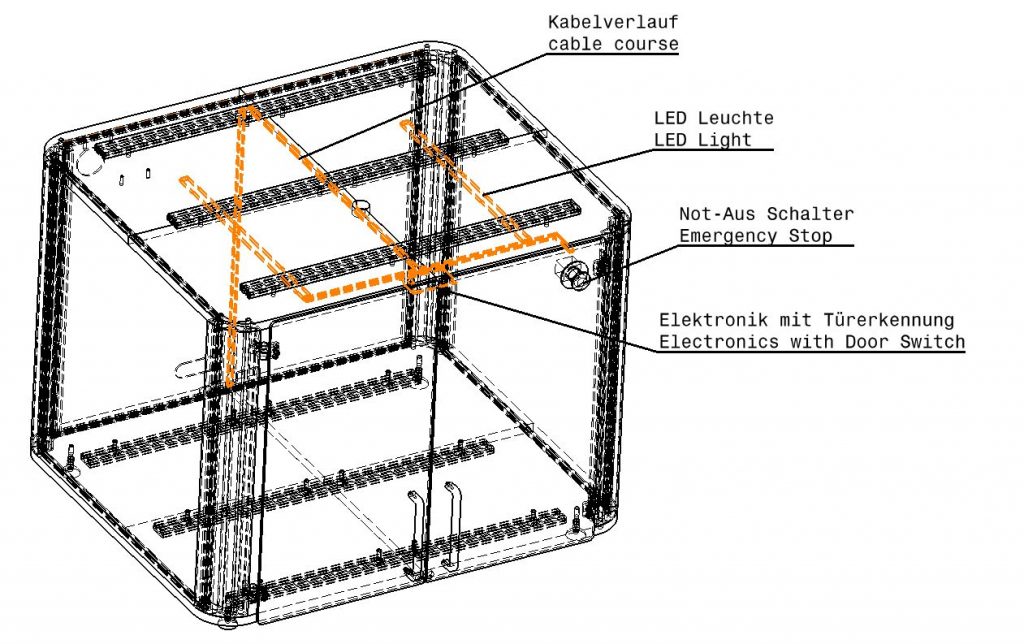
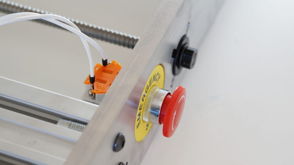
The electronic board of the safety case detects the opening of the doors and automatically stops the milling process. After closing the doors the milling process will start again.

The led lights are activated as soon as the milling machine is powerd up. A red light shows a open door state. Please follow the instructions for full functionality.

Overview of the electronics

The overview of the electronic circuit is displayed in the left picture. The led lights are mounted on the upper plate of the casing. The electronic board with door switch detection is mounted on the front side of the casing.

Both led lights a connected to the electronic board. The electronic board is connected via a control cable with the MINImill control board. The door switch is switched via the magnets mounted to the door panels.

Both emergency stops are connected in series to the MINImill. So each emergency stop has to be open to power up the milling machine.

Mounting the electronics

The electronic board will be mounted with 4 Spax screws on the upper plate.

  • Mount the electronic board with 4 Spax screws and 5mm distance rolls to the upper plate. The door detection switches should look into the direction of the doors – the power connector in direction of the backside.
  • Upload Image...

    LED Lights

    Mount the LED Lights as detailed in the left to the upper plate.

    Connect the electronic

  • Connect the led lamps with the connector on the electronics board.
  • Connect the electronics with the 12V power supply
  • Connect the control cable with the electronic board.
  • Connect your MINImill

  • Connect the control cable to the MINImill control board at the DOOR contact.
  • Connect the emergency stop cable

  • Connect the emergency stop cable of the casing with the emergency stop of the casing. Mount the cables into the orange connector side.
  • Mount the emergency stop with the cover plate into the door panel (Similar to mounting the emergency stop into the milling machine.
  • Emergency stop cable

    Connect the emergency stop cable of the casing with the emergency stop of the milling machine and with the control board as described in the picture. Secure the cables with cable clamps to the top MDF plate.

    Powering up the safety case

    Follow the steps for powering up your safety case:

  • Open all emergency stops. Check whether the cable is connected correctly.
  • Connect the 12V power supply with the grid. The LED lamps are powered up as soon as you power up the milling machine. Connect the milling machine via USB and start the software to switch on the lights.
  • Opening the doors is signaled via a red light. The red light is shown if the control board is connected correctly to the MINImill and if the milling machine is connected via USB.

  • Nächster Schritt

    Klicken Sie auf den Button “Weiter” um zum nächsten Schritt zu gelangen.